Micro-Racer-Guides
Micro Racer Assembly Procedure
Navigation
⚠️ Safety Warning
Electrostatic sensitive components. Please ensure proper grounding before handling.
What You Need
Tools
- Scissors
- Soldering Iron
- Solder
From the Kit
- 1x Micro Racer PCB
- 1x Micro Racer Color Sensor Board
- 1x 300mAh LiPo battery
- 1x Bottom chassis
- 1x Top chassis
- 4x wheel (rim)
- 4x tire
- 4x planetary motor
- 2x motor separator
Assembly Steps
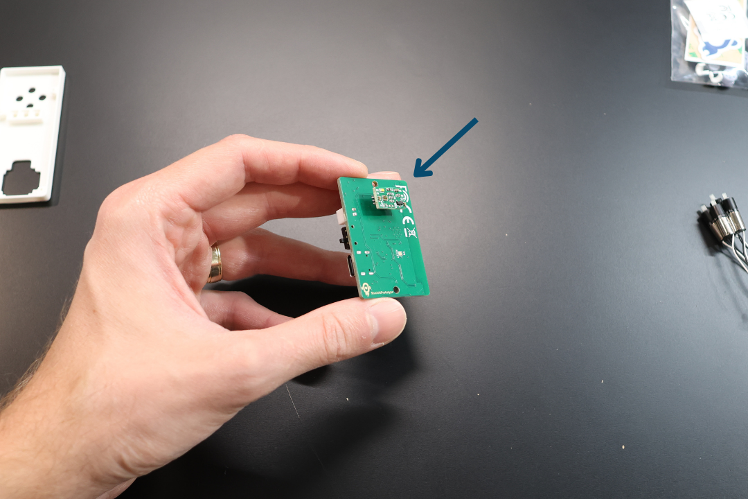
Step 1: Prepare the Sensor
Remove the sensor from the bottom connector on the Micro Racer PCB. Set it aside.
Step 2: Position the PCB
Take the Bottom Chassis and the Micro Racer PCB. Place the Micro Racer PCB on top of the Bottom Chassis as pictured. The bottom connector will go into the opening on the Bottom Chassis.
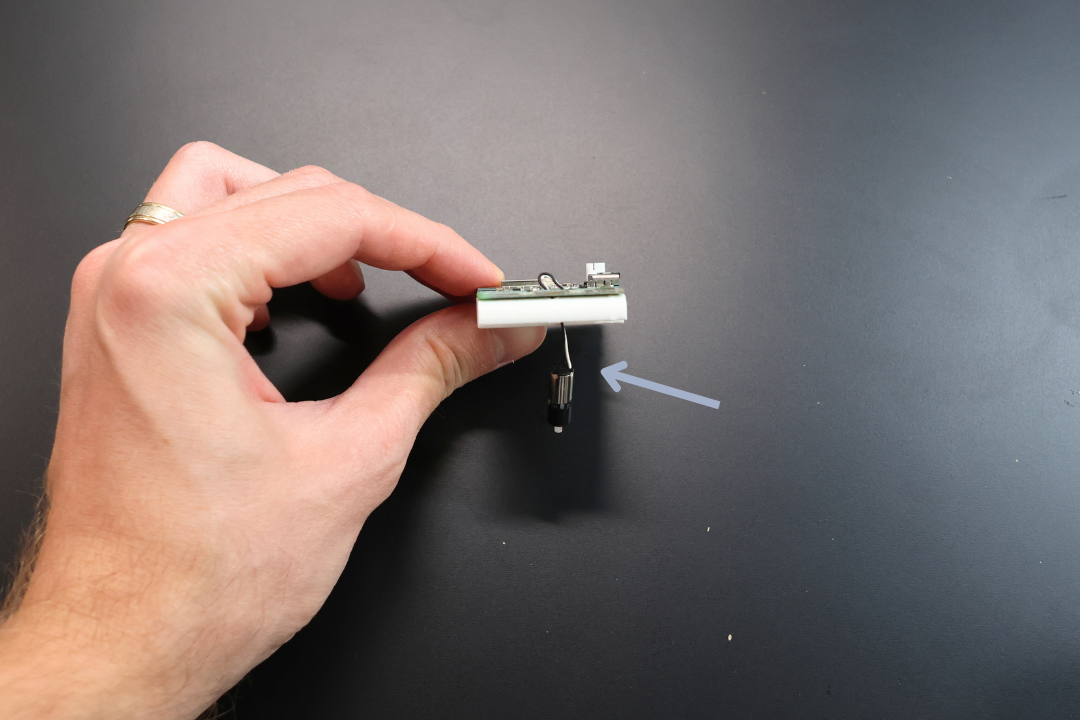
Step 3: Route Motor Leads
Take one of the Planetary Motors and route the leads through the front hole as pictured. Make sure that the wires go through both the plastic and the PCB holes.
IMPORTANT: Do steps 3 through 4 one (1) motor at a time. It is much more difficult if you try doing all motors at the same time.
DO NOT snap the motors into position until all soldering is done. The heat from soldering can deform the plastic.
Step 4: Solder Motor Connections
This is by far the most difficult step, but you got this!
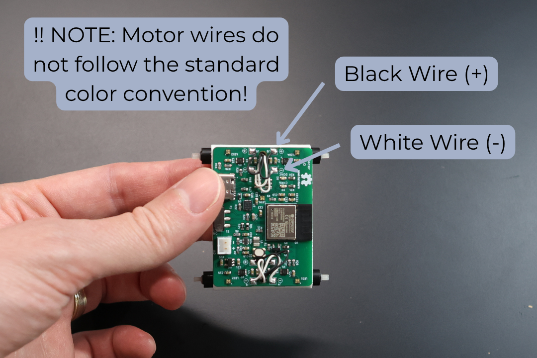
Solder the motor leads to their corresponding connections. You can identify them as follows:
NOTE: The motors do not go by standard convention. The + is soldered to a black lead and - is soldered to a white lead.
| Motor Position | Connection | Wire Color |
|---|---|---|
| Top right motor | J1 (-) | WHITE |
| J2 (+) | BLACK | |
| Top left motor | J4 (-) | WHITE |
| J3 (+) | BLACK | |
| Bottom right motor | J7 (-) | WHITE |
| J8 (+) | BLACK | |
| Bottom left motor | J6 (-) | WHITE |
| J5 (+) | BLACK |
NOTE: Make sure that you do not melt the plastic by separating it as much as possible while soldering. Keeping the motor leads long helps, and they hide nicely under the car body later on.
Solder the motor leads as per the table above. Repeat steps 3 and 4 for each motor one at a time.
Congratulations, you passed the most difficult step. The rest is a breeze! 😊
Step 5: Snap Motors into Position
Snap each motor into its corresponding spot leaving space between the motors for the spacer. You will hear a click, don't be scared, it takes a bit of pressure.
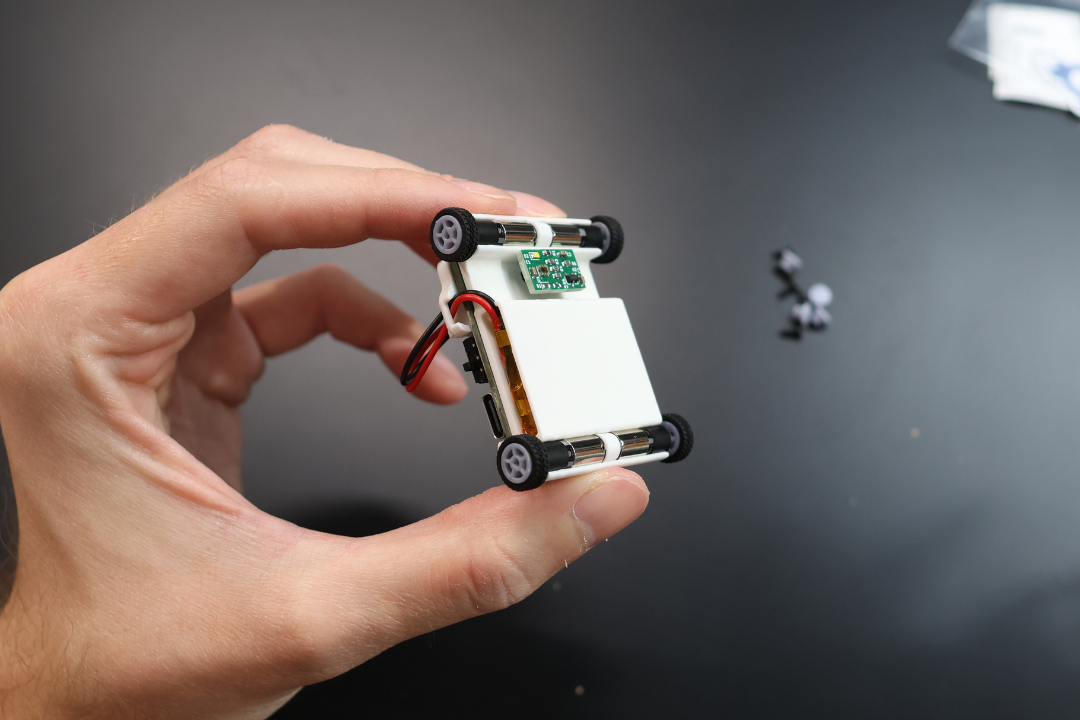
Step 6: Organize Wires
For each motor, once in position, pull the wires to the top as pictured above. Repeat steps 5 through 6 for each motor.
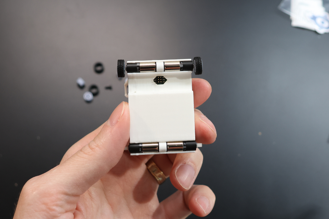
Step 7: Install Spacers
Insert the spacer for each axle.
Step 8: Install Tires
Install tires on the wheels. Note the thread direction, this is only for aesthetics and doesn't really affect the driving characteristics. Refer to the image below.
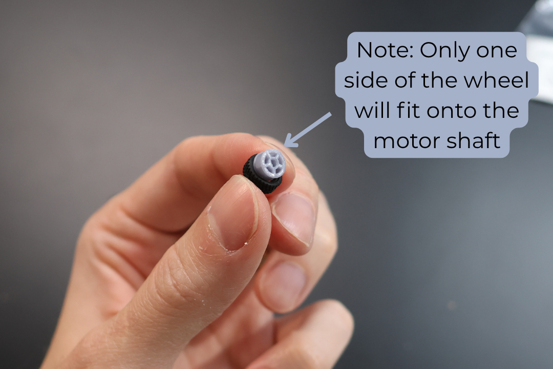
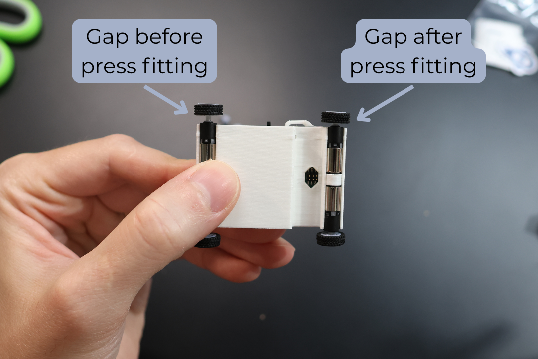
Step 9: Install Wheels
Install the wheels on the motors. As you push the wheels on to the motors you need to align the motors with the chassis. Once aligned, you can push against the opposite sides to ensure the wheels are well secured.
Note: Don't be scared to wiggle the wheels a bit to get them onto the motor shaft. They are press fit and the fitting is fairly tight.
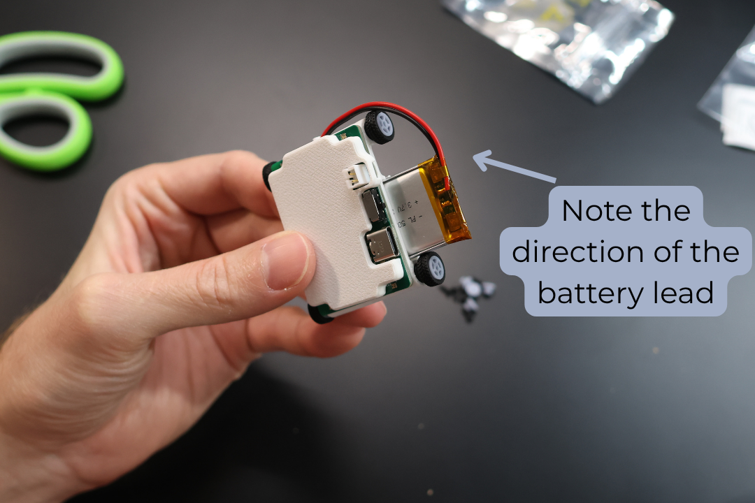
Step 10: Install Battery
Take the 300mAh LiPo Battery provided in the set. Ensure the RED lead is aligned with the (+) on the board. Plug it into the Micro Racer PCB.
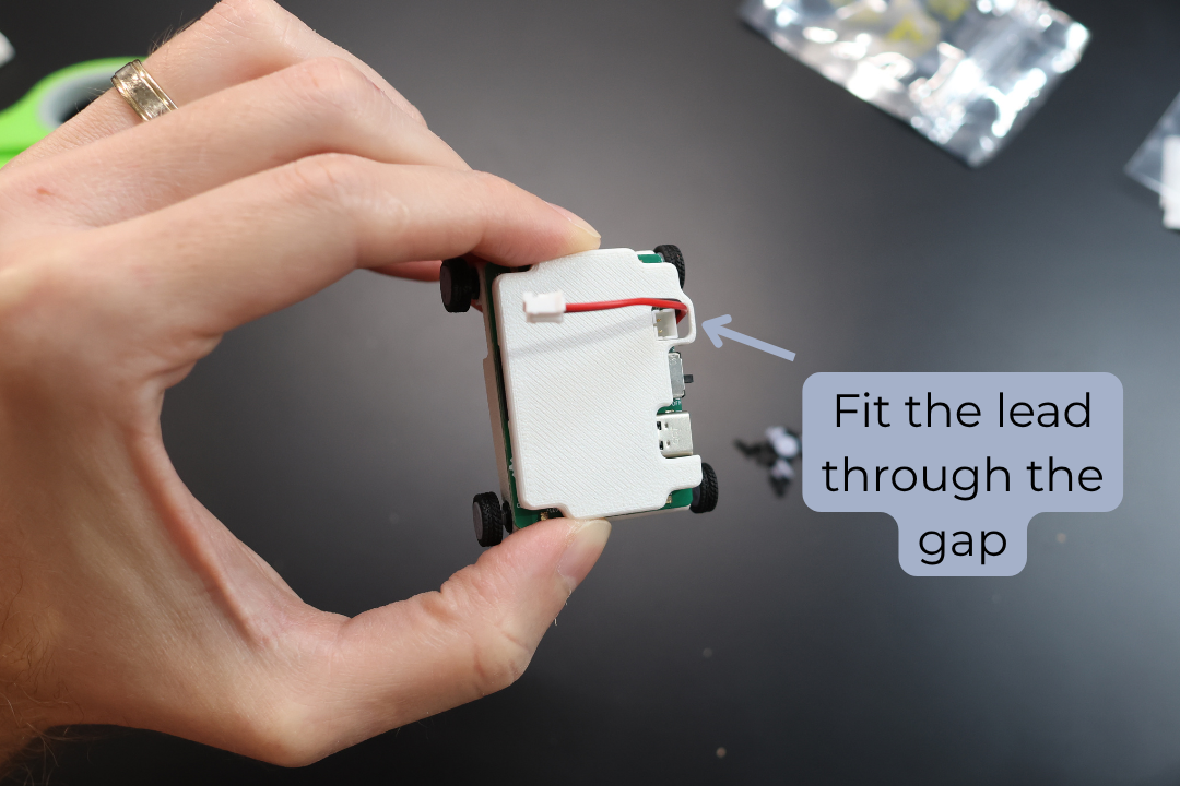
Step 11: Secure Battery
Install the battery into the compartment. Ensure that the battery leads align to the notch towards the front of the car. Fit the lead into the notch.
Step 12: Test the Car
Test the car. Power on the car with the On/Off toggle switch. Turn on the Thumbtroller, make sure the car and the controller connect. The car's headlights will turn on and the top indicator LED on the Thumbtroller will turn blue.
If the motors are not working, please see the Debugging and Troubleshooting Guide on page X
Step 13: Power Down
Turn off both the Micro Racer and the Thumbtroller.
Step 14: Secure PCB
Cut a small strip of the provided double sided tape and place it between the Bottom Chassis and the Micro Racer PCB.
Step 15: Organize Wires
Flatten the extra wire on top of the PCB.
Step 16: Prepare Top Chassis
Cut a small strip of the provided double sided tape and place it on top of the ESP32 (the main controller with a flat silver spot).
Step 17: Install Top Chassis
Place the Top Chassis on top, ensuring it sticks to the tape. Ensure the battery wire goes into the proper position.
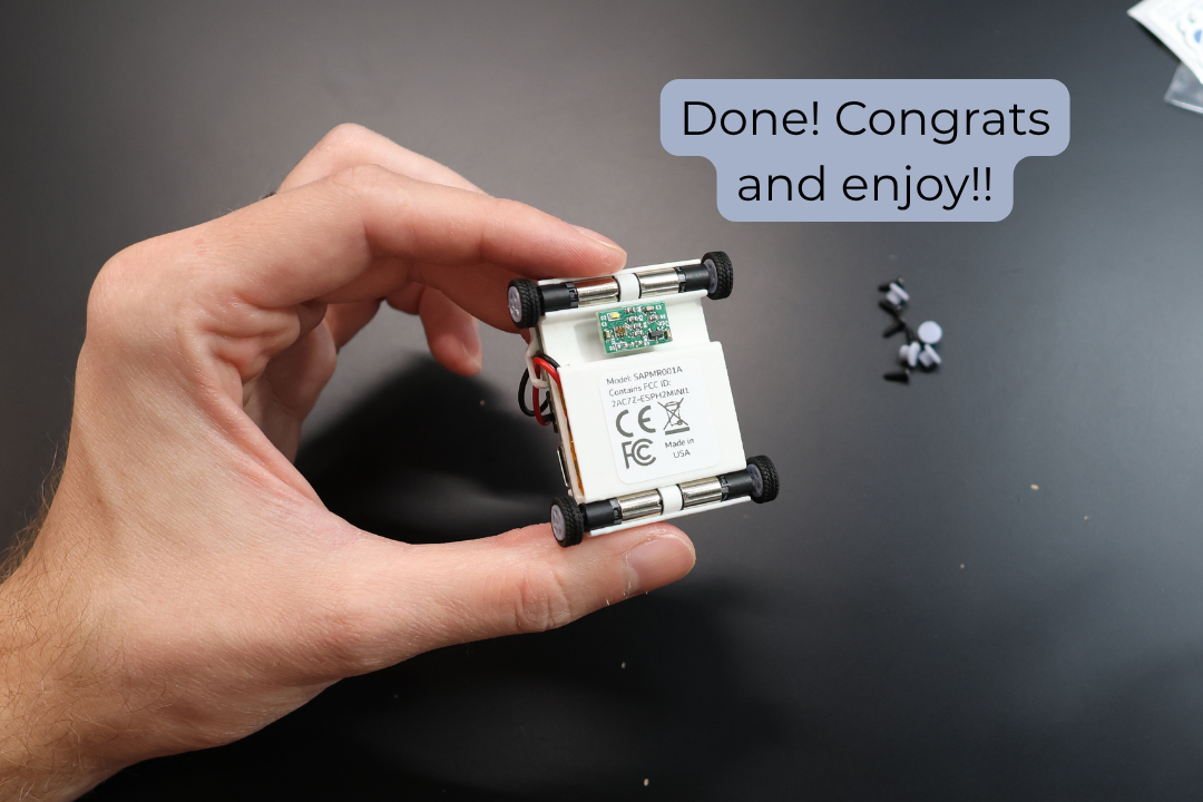
Step 18: Reinstall Sensor
Reinstall the Sensor as pictured. Please make sure the orientation is as pictured.
Step 19: Apply Sticker
Attach the FCC/CE sticker. It gives you extra horsepower! 😉